Type C interface · 11, 15, 24 and 36 kV
Separable connectors, touch-proof terminations and the type C interface
Have four things to hand before reading: conductor cross-section in mm², voltage class, conductor material, and the bushing type printed on the switchgear GA drawing.
The decision, and the inputs it needs
Two things can end a polymeric cable at medium-voltage switchgear. A heat-shrink kit, built onto the cable and bolted to a terminal. Or a separable connector, which plugs onto a standardised bushing. Only four inputs decide between them, and voltage class is the least discriminating of the four.
A separable connector is defined by two properties and nothing else. It mates with a standardised bushing interface instead of a bolted pad, and it can be pulled off and remade on the same bushing without rebuilding the termination. The screen, the submersibility and the insulating plug all follow from those two; none of them defines the category.
Cross-section discriminates harder than kV does. The body covers 25 to 400 mm² at 11 kV and 24 kV, and 95 to 630 mm² at 36 kV. So a 36 kV feeder at 70 mm² falls outside the published connector range and belongs on a heat-shrink kit, whatever the switchgear would have accepted.
Screened separable connector, GEB series
Connects single-core and three-core polymeric cable to medium-voltage switchgear and other equipment through type "C" bushings. Two catalogue variants: 630 A up to 24 kV, and 630/1250 A up to 36 kV in the extended range. Moulded in highly modified EPDM rubber with a touch-proof, earthed outer conductive screen, and range-taking by adapter rather than by body.
- Fully screened and submersible separable connection
- Mates with C-type bushings and plugs complying with EN 50180 and EN 50181
- 24 kV connectors tested and approved at CPRI, India
- Compact design for congested cubicles
| Continuous current | 630 A at 11 and 24 kV; 630 A / 1250 A at 36 kV |
|---|---|
| Cable cross-section | 25–400 mm² at 11 and 24 kV; 95–630 mm² at 36 kV |
| Bushing interface | EN 50180 and EN 50181 type C |
| Cable served | Single-core and three-core polymeric (extruded) cable |
| Body material | Highly modified EPDM rubber, earthed outer conductive screen |
| Range taking | One body with stress-cone adapters across the full cross-section span |
| Lugs | Multi-range compression lugs matched to the connector, in every kit |
| Factory testing | Every connector tested for AC withstand and partial discharge |
Published type-test figures, by voltage class
| Property | 11 kV | 24 kV | 36 kV |
|---|---|---|---|
| Continuous current | 630 A | 630 A | 630 A / 1250 A |
| Alliance bushing | EN 50180 & 50181 Type C | EN 50180 & 50181 Type C | EN 50180 & 50181 Type C |
| AC withstand voltage | 29 kV for 5 min | 54 kV for 5 min | 85 kV for 5 min |
| Impulse withstand voltage, 10 times each polarity | 95 kV | 125 kV | 175 kV |
| Partial discharge at 1.73 U0 | ≤ 10 pC | ≤ 10 pC | ≤ 10 pC |
| Screen resistance | ≤ 5000 Ω | ≤ 5000 Ω | ≤ 5000 Ω |
| Cable cross-section | 25–400 mm² | 25–400 mm² | 95–630 mm² |
Reproduced from the manufacturer's own table. That table prints the AC withstand row twice, the second time with no 36 kV cell; the 11 kV and 24 kV values are identical in both printings, so the row appears once here. U0 is the phase-to-earth voltage of the cable, so 1.73 U0 is a deliberate overstress level for the partial-discharge test, not a service condition.
Sources disagree — 24 kV or 36 kV
The manufacturer's product page is headed Screened Separable Connector up to 24 kV, 630A, and its application list also stops at 24 kV. The body text and the type-test table on that same page publish a second variant at 630/1250 A up to 36 kV. Both statements are published; the page gives no way to reconcile them. Read 24 kV as the standard range and 36 kV as the extended range, and get the 36 kV variant confirmed in writing before it enters a schedule clause.
What is inside the body
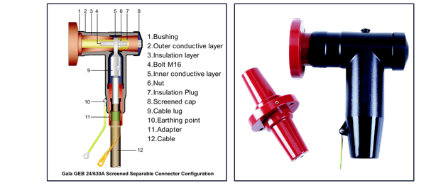
The manufacturer's configuration drawing for the GEB 24/630A numbers twelve parts. Working in from the bushing: outer conductive layer, insulation layer, an M16 bolt, inner conductive layer and nut, closed off by an insulation plug and a screened cap. On the cable side: lug, earthing point, adapter, cable.
Three of the twelve carry the whole electrical argument. The inner conductive layer holds the interior at conductor potential. The insulation layer takes the field across it. The outer conductive layer is bonded at the earthing point, so the field is captured between two conductive surfaces and never reaches an air-exposed insulating surface at all. That is why a screened connector carries no sheds and a heat-shrink outdoor termination does.
The adapter is the range-taking part. One body spans the published cross-section because the stress-cone adapter changes with the cable, not the connector.
What touch-proof means, and what does not qualify
Touch-proof is a construction, not a rating you can apply to an existing part. It needs a continuous earthed outer conductive screen over the entire live interface, taken to earth through a drain wire, so the outside of the assembly sits at earth potential while the conductor inside stays live. Insulation on its own never gets there.
Three items in this catalogue earn the description. The screened separable connector, whose outer conductive layer is bonded at the earthing point. The touch proof protective cap, which electrically insulates and mechanically seals a bushing interface, for permanent or temporary use. And the screened end cap, published as a fully shielded, submersible insulating cover for an energised bushing — but only once its drain wire is grounded. That conditional is the entire mechanism. An ungrounded drain wire leaves an insulating cover and a floating screen.
Two things do not qualify, and the first is stated by the manufacturer rather than inferred here. Of the GTPE-500 elbow terminal protector, the published page says it is not a touch-proof product: it is a one-piece EPDM flashover barrier for entry boxes where phase-to-phase clearance is tight, with dielectric strength above 15 kV/mm and no screen anywhere in it. Nothing else in the terminal protector or bushing boot range is published as screened either, so none of it is touch-proof — those parts insulate, exclude moisture and keep vermin off a live terminal, which is a different job with a different failure mode.
Touch-proof construction is not a work permit
An earthed screen changes what inadvertent contact does. It does not change the isolation, proving-dead and earthing sequence that has to precede work on the circuit, and no clause on this page should be read as permitting work on live plant.
The EN 50181 type C interface
Two standards sit behind the letter C. EN 50180 covers bushings above 1 kV fitted to liquid-filled transformers. EN 50181 covers plug-in bushings above 1 kV on equipment other than those transformers — ring main units, switchgear, GIS. The connector and the end-sealing range are both published as mating C-type bushings and plugs to both documents, because the same interface reaches a distribution transformer under one standard and an RMU under the other.
Read the type off the switchgear general arrangement drawing. Do not infer it from the voltage class: the same 24 kV RMU is built with different bushing types by different makers, and the connector is specified against the bushing the equipment actually carries. Where the drawing does not name a type, ask the switchgear maker in writing before the requisition goes out. The interface is the one dimension in this specification that cannot be recovered on site.
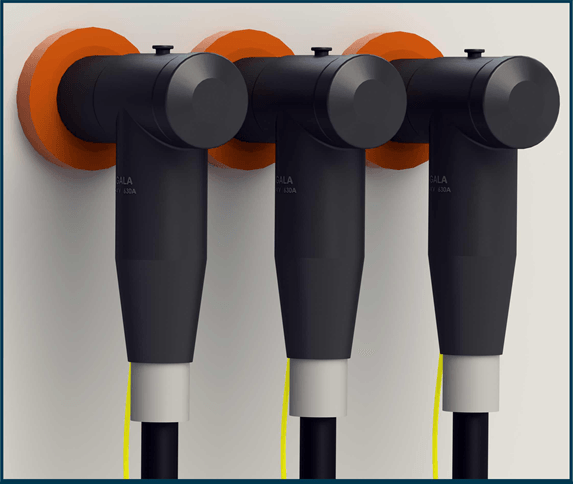
Outer cone and inner cone are different geometries, not different sizes. On an outer-cone bushing the insulating cone faces outwards and the connector body slides over it; on an inner-cone bushing the cone is a socket and the plug enters it. Everything published in this catalogue is the outer-cone type C interface. No inner-cone variant appears anywhere in the manufacturer's data.
Where the current rating actually comes from
The rating is a property of the connector, not of the interface. 630 A at 11 and 24 kV, and 630/1250 A in the 36 kV extended range, are the manufacturer's published figures for this body. They are not what type C means, and a tender clause that quotes them as an interface rating will eventually meet a bushing that does not agree.
No current figure is given here for type A or type B. Those numbers cannot be confirmed against the standard text from the sources this site holds, and a rating written into a specification from memory is worse than a blank left for the switchgear maker to fill.
Not published — ask the manufacturer
Four things this page will not give you, because the published data does not contain them. Which adapter matches which cross-section — the span is published, the mapping is not. Short-time and peak short-circuit withstand current for the connector. Any depth, duration or IP figure standing behind the word submersible. And whether an inner-cone version exists at all. A fifth is a loose end rather than a gap: the datasheet's feature list names a 15 kV class for which no type-test column is printed anywhere. Ask for each on a datasheet, and specify against the datasheet rather than the answer.
Separable connector or heat-shrink termination
Both end the same cable at the same switchgear. They part company on seven axes, and a schedule clause has to settle each one.
| Screened separable connector | Heat-shrink termination kit | |
|---|---|---|
| Interface | Plugs onto an EN 50180 / EN 50181 type C bushing | Lug bolted to whatever terminal the equipment presents |
| Disconnection | Unplugged and remade on the same bushing | Cut back and rebuilt from a fresh kit |
| Live surface | Earthed outer conductive screen over the whole interface | Insulating surface, unscreened, not touch-proof |
| Field grading | Captured between the inner and outer conductive layers | Graded by a stress control tube over the screen cut-back |
| Cross-section | 25–400 mm² to 24 kV; 95–630 mm² at 36 kV | GXO/E codes cover 16–400 mm² at 24 kV and 25–400 mm² at 36 kV |
| Weather exposure | Published as fully screened and submersible | Rain sheds fitted for outdoor duty; indoor kits ship without them |
| Current rating | 630 A, or 630/1250 A in the 36 kV extended range | Published as "as per cable" — set by the conductor and the lug, not by the kit |
Reading the ordering code
The manufacturer publishes the code structure with a worked example: GEBF 24 / 630 185 Al 03 CON. The key beneath it labels six fields, and the example string carries seven elements — so the trailing CON is in the example and defined nowhere. Five of the six labelled fields are numbers you already hold if you have the cable schedule and the GA drawing. Quote the whole string on the requisition rather than a description; a described connector comes back as a question.
GEBF 24 / 630 185 Al 03 CON, field by field
- GEBF / GEBR
- Gala code, F for front and R for rear. The front connector is the tee that goes onto the bushing. The rear connector piggy-backs onto the back of the front body through a copper connecting pipe and a two-headed screw, which is how a second cable lands on one bushing.
- 24
- Voltage in kV. The type-test table prints 11, 24 and 36 kV. The datasheet's feature list names a fourth class, 15 kV, with no test column and no cross-section row behind it.
- 630
- Current rating in amperes. 630 at 11 and 24 kV; 630 or 1250 in the 36 kV extended range.
- 185
- Conductor cross-section of the cable in mm². This selects the adapter, not the body.
- Al
- Conductor material, Al for aluminium or Cu for copper. It sets the multi-range compression lug supplied in the kit.
- 03
- Number of pieces per kit; 03 is the figure in the manufacturer's worked example.
- CON
- A seventh element in the manufacturer's example string that the published key does not define. The key labels six fields and stops at No. of Pcs. / Kit; CON sits after that with nothing against it. Do not add the suffix, or read a meaning into it, without written confirmation of what it changes.
When a separable connector is the right answer
Five conditions. Any one of the first four is sufficient on its own; the fifth is a veto that overrides the other four.
- The switchgear offers only a type C bushing. No amount of heat-shrink makes a bolted lug fit a plug-in interface, and this is by far the most common reason the decision is already made.
- The circuit will be re-entered. A feeder disconnected for testing, extension or load transfer costs a whole kit and a jointer every time it is heat-shrunk, and nothing at all when it unplugs.
- The termination may be flooded. Submersible service is published for the connector and for the screened end cap. Across this whole termination catalogue it is published for no heat-shrink termination kit.
- The cubicle must be dead-front. Where the specification requires that nothing live is exposed to touch inside the enclosure, only the earthed outer screen delivers it — an insulating cover does not.
- The cross-section must be inside the published band. 25 to 400 mm² at 11 and 24 kV, 95 to 630 mm² at 36 kV. Outside it, the answer is a heat-shrink kit however strong the other four arguments are.
- It is not the answer where the cable ends in air rather than on a bushing — a pole or gantry termination — because there is no interface to plug into. See indoor or outdoor for that decision.
Questions this page gets asked
Is a screened separable connector the same thing as a touch-proof termination?
What does 1.73 U0 mean in the partial-discharge row?
Does a separable connector need rain sheds?
Can I fit a 36 kV connector to a 70 mm² cable?
Is the type C interface the same on a transformer and on an RMU?
What third-party testing exists behind these figures?
Send four numbers, get a code back
Cross-section in mm², voltage class, conductor material, and the bushing type from the GA drawing. That is enough to return a connector code and the matching adapter without a second round of email.