Transformers & motors
Terminating at transformers and motor terminal boxes
Two machines, and neither behaves like a panel: one gets opened on a test schedule, the other shakes and heats every time it starts.
The decision, and the two machines that fork it
Nothing on this page makes a connection. The kit and the compression lug did that; what is chosen here is the material occupying the air around a finished joint on a machine.
Six inputs settle it: machine type and bushing geometry, Umax, cable insulation and core count, conductor cross-section in mm² with round or sector noted below 3.3 kV, whether the joint is broken again on a maintenance schedule, and the measured clearance left once three phases are inside the enclosure.
The fifth is the one a panel never forces you to answer. A transformer is opened for ratio checks, insulation resistance and tap work; a motor terminal box is opened for every rewind. Both are recurring events with dates against them, so reuse decides the part before any dimension does.
Which side of the transformer the cable is on
The manufacturer's connector data records the interface as EN 50180 & 50181 Type C at 11 kV, 24 kV and 36 kV. The pair is cited together because the two standards divide by equipment: EN 50180 is the bushing standard written for liquid-filled transformers, EN 50181 the one for plug-in bushings on equipment that is not a liquid-filled transformer. A transformer is the one machine where the first half of that citation is the operative half.
Where the transformer presents that plug-in geometry, the screened separable connector is the termination and nothing is fitted over it. Where it presents a stud, a palm and a bolted lug — as most distribution units in the field still do — a heat-shrink kit finishes the joint and the cover over it becomes the decision.
The other split is HV against LV. A distribution transformer has a medium-voltage side, which is what this site is about, and a low-voltage side that is mostly ducting, glanding and a four-core cable. Parts from the two sides reach the store on one delivery note and get confused more often than any other pair here.
Four machine conditions, and what each one takes
Read the first line off the equipment, not off the cable schedule. The cable schedule confirms a size; the machine chooses the family.
Distribution transformer, terminated in the open
A plinth or pole unit is an outdoor termination in the strict sense: wetting, pollution, and a creepage path that has to survive both. The kit is the outdoor build with sheds fitted, and shed count is a separate calculation from anything on this page.
Transformer with a cable box or a marshalling wall
The joint is made indoors and left made for years at a time. Here a non-tracking elastomeric boot over the finished bushing connection is enough — GSBB-1 or GSBB-2 on a 46 to 70 mm bushing, in a right-angled or straight profile to match how the tail approaches. Its published ceiling is the one thing three of the manufacturer's documents will not agree on.
Transformer opened on a test schedule
Ratio, insulation resistance and tap work all mean the cover comes off and goes back on. Only the reusable silicone/rubber construction is catalogued to be taken off and refitted as often as needed. It is one code, GRRB-1, sized on measured bushing diameter across 46 to 70 mm rather than on voltage.
Motor terminal box
The tightest enclosure any distribution cable ends in, and the only one bolted to a rotating machine. The EPDM barrier system is the published answer: boot, grommets and plug, re-usable, and stated to fit sector-shaped cable. Its cross-section ceiling is the one figure the manufacturer's own documents give twice and differently.
The motor terminal box
A terminal box is not a cable box. Its volume follows the motor frame, its gland plate follows the conduit run, and the three lugs land wherever the stator leads reach — so phase-to-phase clearance is a leftover rather than a dimension anybody chose.
Hence a barrier system rather than a boot per phase. It is injection-moulded EPDM, highly insulating and track-resistant, establishing phase-to-phase-to-earth insulation across the enclosure while insulating right-angle connections. Distribution transformers and motor terminal boxes are two of the four settings the manufacturer names for it; charts are at cable terminal protectors.
Sector-shaped conductor is the detail that catches requisitions out. The barrier system explicitly claims a sector fit; the crutch seal below it does not. Insulcore-LV covers PVC, XLPE, rubber and paper cable of two to seven cores up to 3.3 kV, in cross-linked polyolefin lined with hot melt adhesive and rated IP68 once installed — but its chart is dimensioned on diameters and states no sector allowance. Send the real make-up, not an equivalent round size.
Two duties belong to this end of the run alone. The box vibrates continuously with the machine and cycles thermally with every start and stop, so the seal at the lug is worked mechanically in a way a wall-mounted transformer termination never is. Nothing in the sources qualifies any part here against either, so it stays an open question in the enquiry.
Not published — ask the manufacturer
Three facts a motor or transformer clause routinely asks for do not exist in the source documents. Vibration qualification — no test, no cycle count, no acceptance criterion, at either machine. A sector-shape tolerance for the crutch seal — the Insulcore-LV chart is dimensioned on diameters only, while the barrier system above it claims sector fit outright. Any mapping from motor frame size or terminal-box internal dimension to a barrier code — the published selection fields are cross-section and bushing centre distance, neither of which appears on a motor datasheet. Thermal cycling is not on this list: the catalogue's type-test particulars publish a heating cycle in air at 3 cycles and again at 60 cycles for indoor and outdoor terminations, 5 hours heating and 3 hours cooling, at 16, 30 and 45 kV AC, with no breakdown and no flashover required. Nor is the boot diameter: both elastomeric boots are published for bushings of 46 to 70 mm.
Bellows belong to the low-voltage side
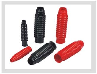
A bellows is a flexible PVC ducting article, published for cable entry into low-voltage switchgear and transformer equipment and supplied in several profiles to suit the mounting.
It is named here because of where it sits: on the LV side of the same distribution transformer whose HV side is being terminated, ordered on the same requisition, and moulded in the same red and black as the boots it is nothing like.
No voltage class is assigned to it anywhere in the source material, so it cannot be counted toward a clearance or written into an insulation clause. It is an entry-and-ducting line item. Source: the manufacturer's bushing boot and bellows page.
What to put in the enquiry
Each line below moves the part number. A missing line is the difference between a code in one reply and a code in six.
- The machine: transformer or motor, and for a transformer whether the bushing is a stud-and-palm or a Type C plug-in.
- The maintenance regime in plain words: how often the joint is broken, and for what. This is the reuse answer, and it outranks every dimension.
- Bushing outside diameter in millimetres, measured, wherever a reusable boot is in scope; nothing outside 46 to 70 mm is catalogued.
- Bushing centre distance where a barrier system is in scope, taken off the general arrangement rather than scaled from a photograph.
- Umax for the system, not the nameplate voltage stamped on the machine.
- Cable insulation, core count and conductor cross-section in mm² — and for anything at or below 3.3 kV, whether the conductors are round or sector-shaped.
- Whether the termination stands in the open. A plinth-mounted transformer is an outdoor job needing the outdoor build and its sheds, which no boot or barrier substitutes for.
Questions that arrive with transformer and motor enquiries
Is there a termination kit specifically for transformers?
Which part goes into a motor terminal box on sector-shaped cable?
Can the cover stay on for a routine insulation test?
Does anything reach 66 kV at a transformer bushing?
The transformer sits outdoors on a plinth. Does that change the cover?
Specifying at a machine rather than at a panel
Name the machine, the bushing geometry, the maintenance interval that breaks the joint, and the cable feeding it. Those four settle the family; measured dimensions then settle the code.