GTPE-500 · GSTB / GRTB · GOC · 12 kV and 24 kV
Cable terminal protectors for compact entry boxes
Barrier hardware for the case where the enclosure is too small for air alone to do the insulating.
The decision, and the data that settles it
Three fields name a terminal protector. The form the connection needs — straight, right-angle or one-piece elbow. The bushing centre distance in millimetres, read off the panel GA: 95 mm for the GTPE-1, 110 mm or 125 mm for the GSTB and GRTB codes. And the rated voltage of the enclosure, 12 kV or 24 kV.
Conductor cross-section is a compatibility check rather than a selector, and the two sources do not agree on where it stops. Both datasheets print 25 sq mm to 400 sq mm; the manufacturer's product pages print 25 sq.mm to 300 sq.mm. Sector-shaped conductors are included either way, and no code in any of the three selection charts moves with cross-section.
Two voltage conventions run through the source sheets and both are reproduced here: the feature lines are written for 11 kV and 22 kV systems, the withstand table is headed 12 kV and 24 kV. Read them as one pair of classes written twice, once as system voltage and once as Um.
A barrier is specified after the termination method is settled, never in place of it. It occupies the air around a finished connection; field grading, screen cut-back and sealing belong to the termination kit and its components.
Three families, three different conditions
They share a page because they answer one complaint — too many live parts in too little air — and nothing else.
GTPE-500 elbow protector
One piece, moulded in EPDM, for a cable entry box where phase-to-phase clearance is tight and air alone would not give adequate insulation. Published as fitting epoxy bushings and compact type C RMU bushings, with withstand figures at 12 kV and 24 kV.
GSTB and GRTB barrier system
An insulating boot, grommets and a plug, giving phase-to-phase-to-earth insulation across a terminal group. GSTB is the straight form, GRTB the right-angle one. Bushing pitch fixes the suffix: 110 mm centres take the −1 codes at 12 kV, 125 mm the −2 codes at 24 kV.
GOC insulation boot
Switchgear hardware, not a cable accessory. Non-tracking cross-linked polyolefin over the primary contacts of a draw-out circuit breaker in an MV or HV substation, to ANSI C37.20.2, in four sizes to 800 sq.mm.
Cable terminal protector GTPE-500
A one-piece elbow moulding that occupies the air between a terminated phase and its neighbours inside a compact cable entry box, published as a barrier against flashover rather than as a touch-proof cover.
- Re-usable, and re-fitted after a test without replacement
- Permits direct voltage testing with the barrier in place
- UV resistant and tracking resistant
- Fits sector-shaped cables
- Economically viable at 11 kV and 22 kV, in the manufacturer's own wording
| Rated voltages published | 12 kV and 24 kV |
|---|---|
| Cable range | 25 sq mm to 400 sq mm on the datasheet; 25 to 300 sq.mm on the product page |
| Bushing centre distance | 95 mm (GTPE-1) |
| Bushing types | Epoxy bushings; RMU type C, compact design |
| Material | EPDM rubber, injection moulded |
| Dielectric strength | 15 kV/mm min. [ASTM D149] |
| Hardness | 35 ± 5 Shore D [ASTM D2240] |
| Continuous temperature limit | −40 to +115 °C [IEC 216] |
| Touch-proof | No — stated as such by the manufacturer |
| Production testing | Factory tested |
Selection chart — GTPE-500 elbow protector
| Product code | Application voltage (kV) | Bushing centre distance (mm) |
|---|---|---|
| GTPE-1 | 12 | 95 |
Printed on the GTPE-500 datasheet (Issue 1, January 2024) under the heading 'Selection Chart — Right Angle Boot'. One code, one voltage, one pitch. Centre distance is in millimetres, measured between adjacent bushing axes on the panel plate.
GTPE-500 withstand tests
| Test | Rated voltage 12 kV | Rated voltage 24 kV |
|---|---|---|
| AC high-voltage withstand, 1 min duration | 28 kV | 50 kV |
| Impulse withstand test | 75 kV | 125 kV |
GTPE-500 physical properties
| Test description | Recorded value | Test method |
|---|---|---|
| Tensile strength | 10 N/mm² (MPa) min. | ASTM D638 |
| Ultimate elongation | 200 % min. | ASTM D638 |
| Water absorption | 0.5 % max. | ASTM D570 |
| Hardness | 35 ± 5 Shore D | ASTM D2240 |
GTPE-500 thermal properties
| Test description | Recorded value | Test method |
|---|---|---|
| Continuous temperature limit | −40 to +115 °C | IEC 216 |
GTPE-500 electrical properties
| Test description | Recorded value | Test method |
|---|---|---|
| Dielectric strength | 15 kV/mm min. | ASTM D149 |
| Volume resistivity | 1 × 10¹³ min. | ASTM D257 |
| Dielectric constant | 5 max. | ASTM D150 |
Volume resistivity is printed on the source sheet with no unit against it, and is reproduced here exactly as published. The comparable row on the circuit-breaker boot sheet further down is given in Ohm·cm.
The GTPE-500 is not a touch-proof product
That sentence is the manufacturer's, not an inference drawn here. An insulating barrier lowers the touch voltage on a surface; it does not carry the surface to earth, and nothing in this family has an earthed outer screen. Where the specification calls for a dead-front connection, the part that satisfies it is the screened separable connector, and the barrier is the wrong object to argue about.
The barrier system: boot, grommets and plug
The GTPE-500 covers one connection. GSTB and GRTB enclose the terminal group: the boot takes the cable tail, the grommets close it around the conductor, the plug fills an aperture that is not being used. All three are injection-moulded from EPDM, which is both highly insulating and track-resistant, and the assembly insulates a right-angle connection as readily as a straight one.
Published applications are motor terminal boxes, ring main units, distribution transformers and any densely populated installation area. Two named failures sit behind that list: flashover in a humid HT cable entry box, and a short circuit started by a reptile, a bird or another animal bridging live parts.
It comes apart. Direct voltage testing with the barrier in place is a published feature, and because the parts are re-usable rather than shrunk on, a test that does need them off costs only the time to refit.
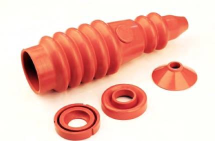
Selection chart — straight boot
| Product code | Application voltage (kV) | Bushing centre distance (mm) |
|---|---|---|
| GSTB-1 | 12 | 110 |
| GSTB-2 | 24 | 125 |
Selection chart — right-angle boot
| Product code | Application voltage (kV) | Bushing centre distance (mm) |
|---|---|---|
| GRTB-1 | 12 | 110 |
| GRTB-2 | 24 | 125 |
Centre distance is taken between adjacent bushing axes on the panel plate, not across the fitted boots. It is a selection field in both charts and there is no cable-size column in either.
Sources disagree: 300 sq mm or 400 sq mm
Both published datasheets — the GSTB/GRTB sheet and the GTPE-500 sheet — read Suitable for Cable range from 25 sq mm to 400 sq mm. All three of the manufacturer's own product pages read 25 sq.mm to 300 sq.mm. The datasheets are the later documents and the GTPE-500 one is dated January 2024, which is an argument but not a resolution. Nothing here reconciles them. If the design sits between 300 and 400 sq mm, that is the one number worth confirming in writing before the order goes out.
Not published — ask the manufacturer
Three fields a barrier clause usually wants are absent from the source sheets. No pollution class is stated for any of the three families. No partial-discharge level is published. And the GTPE-500 volume-resistivity figure carries no unit. A fourth is a mismatch rather than a gap: the GTPE-500 selection chart carries one code, GTPE-1, at 12 kV and 95 mm centres, while the withstand table beside it runs a 24 kV column — so whatever code covers 24 kV on that pitch is not named anywhere in the published record. Get all four in writing before any of them reaches a drawing.
The GOC boot, and why it shares this page
This one belongs to the switchgear. It insulates the draw-out circuit breaker in an MV or HV power plant or substation, and it earns a place beside the cable-side barriers because the constraint is identical.
Everything else about it differs. The material is non-tracking cross-linked polyolefin instead of EPDM — halogen free, flame retardant, resistant to UV and ozone, and published as protecting against chemical corrosion by acid, alkali and salt. Tensile strength is 13 N/mm² min. [ASTM D638], hardness 45 ± 10 Shore D [ASTM D2240] and density 1.20 ± 0.2 g/cm³ [ASTM D792]. It meets ANSI C37.20.2, ships complete with fasteners, and is installed or taken off again in minutes as often as required.
Full sheet: switchgear insulation products.
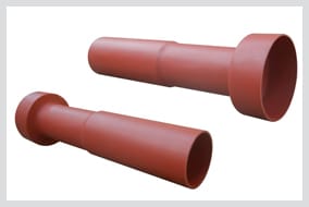
GOC insulation boot — selection chart
| Code no. | Size (mm) | Conductor size (sq.mm.) | Packaging (m/roll) |
|---|---|---|---|
| GOC 1 | 14 | ≤ 70 | 20 |
| GOC 2 | 18 | 70 – 185 | 20 |
| GOC 3 | 31 | 185 – 400 | 20 |
| GOC 4 | 38 | 400 – 800 | 20 |
GOC insulation boot — thermal properties
| Property | Value | Standard |
|---|---|---|
| Accelerated ageing 120 °C / 168 h — tensile strength | 11 N/mm² (MPa) min. | ASTM D638 |
| Accelerated ageing 120 °C / 168 h — ultimate elongation | 250 % min. | ASTM D638 |
| Low-temperature flexibility, −40 °C for 4 h | No cracking | ASTM D2671 |
| Heat shock, 250 °C for 30 min | No cracking or flowing | ESI 09-11 |
| Flammability (oxygen index) | ≥ 28 | IEC 93 |
| Continuous temperature limit | −40 to +105 °C | IEC 216 |
GOC insulation boot — electrical properties
| Property | Value | Standard |
|---|---|---|
| Dielectric strength | 25 kV/mm min. | IEC 243 |
| Volume resistivity | 1 × 10¹⁴ Ohm·cm min. | ASTM 2303 |
| Dielectric constant | 5 max. | ASTM D150 |
| Resistance to tracking and erosion | No tracking, erosion or flame failure up to 3.25 kV for 20 min | ASTM D2303 |
Technical qualification report 1036 is cited on the published sheet against this table.
Sources disagree: the GOC test methods
Two rows of the boot table cite a method that does not match the property beside it. Volume resistivity is referred to ASTM 2303 — ASTM D2303 is the inclined-plane tracking and erosion test, and it is cited again three rows on for tracking, while the same property on the GTPE-500 sheet is referred to ASTM D257. The oxygen-index row is referred to IEC 93, which covers volume and surface resistivity of solid insulating materials. Both rows are reproduced above as published rather than corrected here. Confirm the method with the manufacturer before either figure is written into a clause.
What a terminal protector is not
Four things a barrier is regularly asked to do that it does not do, each with the part that does.
- Not a field-grading component. It changes nothing about the stress at the screen cut-back. That duty stays with the stress control tube inside the termination.
- Not a termination. It carries no conductor, makes no connection and forms no seal onto the cable. It goes on after the kit, over the finished work.
- Not an outdoor part. The barrier system is published for indoor terminations in compact enclosures. Outdoors the governing quantity is creepage extension rather than enclosure clearance, which is a different decision entirely.
- Not a bushing boot. A boot pulled over a completed straight or right-angled bushing connection is a separate family with its own sizing and its own standard — see bushing boots.
Questions a requisition raises
How do I choose between GSTB and GRTB?
Does the cross-section range decide the part number?
Can the cable be voltage-tested with the protector fitted?
What is the highest voltage published for these barriers?
Is the GOC boot interchangeable with the EPDM barriers?
Does fitting a barrier let the phase spacing in the box be reduced?
Specifying a barrier for a compact box
Send the boot form, the bushing centre distance, the enclosure's rated voltage and the cable size, and the reply can name a code instead of a family. The manufacturer's own GSTB/GRTB page carries the same two charts.