RMU & bushings
The ring main unit, and what happens where the cable meets it
Ring main unit: compact MV switchgear that feeds a distribution ring from either direction and isolates a faulted section without dropping supply downstream.
The decision, and the data that settles it
Five fields decide the cable-side hardware: cable make-up, core count, cross-section in mm², the unit's Umax, and whether the way is live now or held spare.
The sixth is the bushing, read off the switchgear GA drawing rather than the enquiry. Where it is a type C bushing to EN 50180 and EN 50181, every connector, cap and sealing kit below mates to that published geometry. Where the unit has a conventional cable box instead, none of them apply.
This page stops at the bushing flange. Interrupting rating, busbar arrangement, switch mechanism and protection scheme belong to the switchgear maker. The subject here is the cable, the air around it, and the accessory occupying that air.
Vocabulary on a cable-side RMU drawing
- Type C bushing
- The plug-in interface named in EN 50180 and EN 50181. Connectors, caps and sealing kits are published as mating with C-type bushings and plugs to both.
- Extensible bushing
- A way brought out for a circuit not yet laid. It can sit energised behind the panel wall with nothing plugged into it.
- Screened end cap
- A fully shielded, submersible cover for an energised bushing, valid as screened only once its drain wire is earthed.
- Touch-proof protective cap
- The unscreened member of the same kit family. It insulates and mechanically seals the interface, and carries no drain wire.
- Bushing centre distance
- Pitch between adjacent phase bushings. A selection field, not a note: the GTPE-1 elbow is charted at 95 mm, the GSTB and GRTB boots at 110 mm for 12 kV and 125 mm for 24 kV.
- Dead-front
- A connection whose outer conductive screen is earthed, so its exterior may be touched. Only the screened separable connector is offered as touch-proof.
Four ways the cable side gets terminated
Each is selected by a different condition. They are not tiers of quality and they are not interchangeable.
Screened separable connector
630 A up to 24 kV, or 630/1250 A up to 36 kV, tested in compliance with [IEC 60502.4]. Modified EPDM with an earthed outer screen: dead-front, submersible, re-enterable. One body plus stress-cone adapters covers 25–400 mm² to 24 kV and 95–630 mm² at 36 kV.
Heat-shrink termination into the cable box
For a unit with a cable box rather than a plug-in bushing. GXO/E for XLPE and EPR, GPO/E for PILC, from GXO/E-1112 at 12 kV to GXO/E-3336 and GPO/E-3336 at 36 kV. Indoor and outdoor builds are catalogued separately; an RMU box takes the indoor one.
Bushing boot over a finished connection
A non-tracking elastomeric boot pulled over a right-angled or straight bushing connection, raising phase-to-phase and phase-to-earth insulation against flashover or induced surges. It covers a connection rather than making one, so it is specified after the termination method.
EPDM terminal protector barrier system
GTPE-500, a one-piece elbow protector for compact type C bushings: AC withstand 28 kV for 1 min at 12 kV and 50 kV at 24 kV, impulse 75 kV and 125 kV, dielectric strength 15 kV/mm min [ASTM D149]. GSTB/GRTB is the straight and right-angle pair.
What selects each, and where each stops
| Method | Selected by | Published limit | What it does not do |
|---|---|---|---|
| Screened separable connector | Dead-front duty, flooding, or re-entry expected | 630 A to 24 kV; 630/1250 A to 36 kV; PD ≤ 10 pC at 1.73U0; screen resistance ≤ 5000 Ω | Nothing at all for a unit without a type C bushing |
| Heat-shrink termination | Cable box entry, no plug-in bushing on the unit | 1.1 kV to 36 kV across the GLT, GPO/E and GXO/E series | Not published as re-usable, unlike the EPDM barriers |
| Bushing boot | A finished connection needing more insulation margin | Sources disagree — see the note below | Carries no interface duty; it is an over-cover only |
| EPDM terminal protector | Phase-to-phase clearance too tight for air alone | Cross-section disputed — 400 mm² or 300 mm²; charted at 95, 110 and 125 mm centres | GTPE-500 is stated not to be a touch-proof product |
Sources disagree — bushing boot voltage
The manufacturer's bushing boot page states insulation of switchgear bushing connections up to 25 kV in its description, and tested to ANSI C37.20.2 for MV switchgear application up to 36 kV in the feature list on the same page. Both are reproduced here as published. Neither is averaged, and neither belongs in a schedule clause without the type-test report for the Umax specified.
The extensible bushing, and why an empty one is still specified
An extensible unit is bought with spare ways so a feeder can be added later without a new panel. Each spare way is a bushing with nothing on it, and an uncovered bushing end is a moisture path into the interface a future circuit must land on.
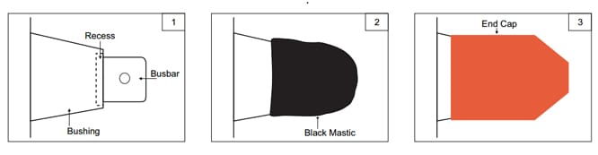
The end sealing kit closes it in three moves: black mastic into the recess behind the busbar spade, heat-shrink material drawn down over the bushing body, cap over the end. Unscreened insulates and seals; screened adds the shield and the earthed drain wire and is rated submersible.
The datasheet sets the ceiling by cover type rather than by code: unscreened up to 11 kV, screened with ground up to 36 kV. The product page for the same kit lists 11 kV, 15 kV and 24 kV instead. Four sizes are published in the GEK and GSEK series. The insulation layer is published at 12 kV/mm dielectric strength min [ASTM D149], 1 × 10¹⁴ Ω·cm volume resistivity min [ASTM D257], no tracking or erosion up to 3.25 kV for 20 minutes [ASTM D2303], continuous limit −40 to +100°C [IEC 216].
The cap comes off when the way is used — the argument for sealing a spare bushing rather than potting it. Codes, bore diameters and the two conflicting class lists sit on end sealing kits, caps and covers.
What each accessory looks like on the wall
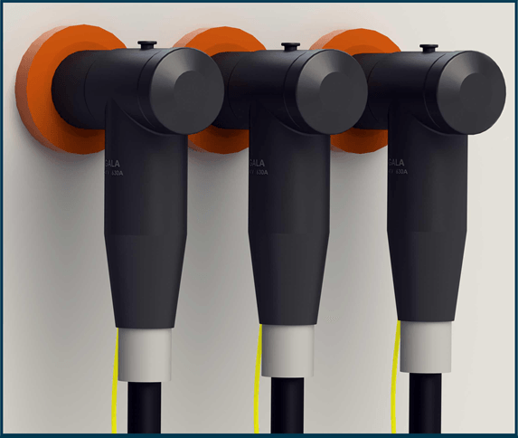
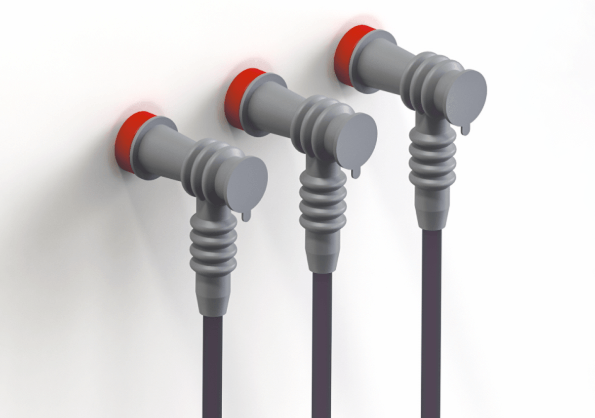
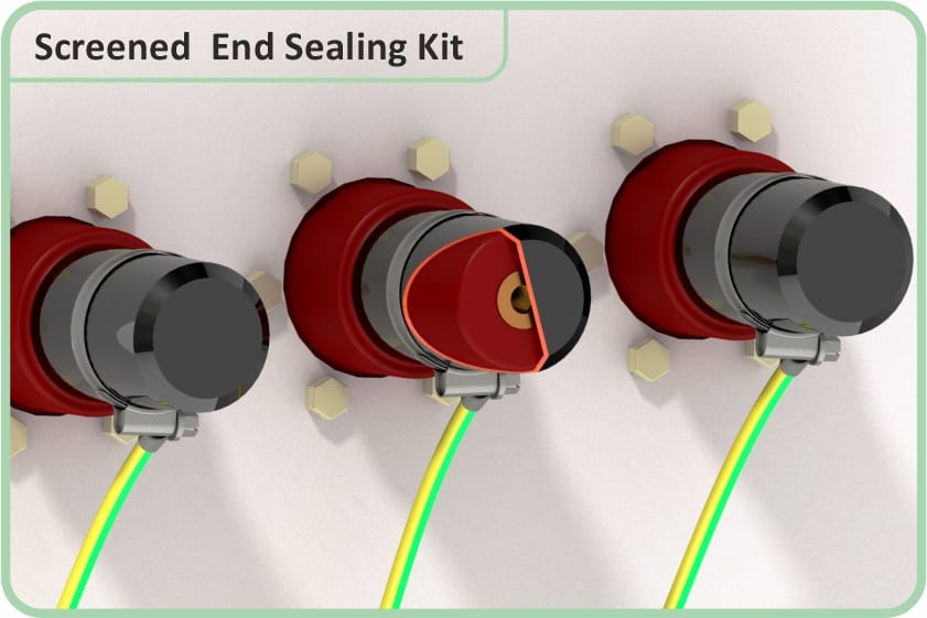
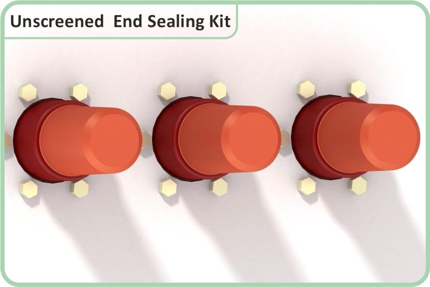
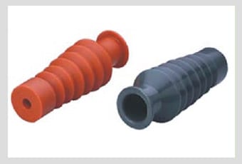
The tightest clearances in a distribution network
Three phases terminated inside a compact entry box is the smallest air volume in the network. The GTPE-500 exists for that case: phase-to-phase clearance limited, air alone not adequate insulation, a barrier needed against flashover.
Three charted pitches show how little room there is: the GTPE-1 elbow at 95 mm centres, and the GSTB and GRTB boots at 110 mm for 12 kV and 125 mm for 24 kV. Where the cross-section stops is the one number the sources will not settle, so it cannot carry an argument on its own.
The tight box also rules out the outdoor habit of buying surface distance with shed rings. A creepage extension skirt earns its length radially, as a stack of shed diameters around the core, and radial room is what a 110 mm pitch lacks. See indoor versus outdoor terminations and the sizing under rain sheds.
Two further published claims belong in a specification rather than a brochure: the barriers prevent flash-over from humid environments in HT cable entry boxes, and protect against short circuit from reptile, bird or animal intervention. They also facilitate direct voltage testing, are re-usable, and fit sector-shaped cables.
Sources disagree — barrier cross-section
The GSTB/GRTB and GTPE-500 datasheets both print a cable range of 25 sq mm to 400 sq mm. The manufacturer's three product pages for the same parts print 25 sq.mm to 300 sq.mm. That gap decides whether a 400 mm² feeder into an RMU can take a barrier at all or has to be a separable connector question, and nothing published settles it. Ask for the figure against the specific code before the box layout is fixed. The charts and both wordings are on cable terminal protectors.
Not published — ask the manufacturer
Three things an RMU clause usually needs are absent from the source documents. The pollution class the GTPE-500 is qualified against is not stated. The GTPE-500 chart names one code at one voltage — GTPE-1, 12 kV, 95 mm centres — so no code is published for a 24 kV enclosure even though the withstand table carries a 24 kV column. And no published document maps the GEK, GSEK and touch-proof covers onto the voltage classes their own headings name.
Questions asked at the requisition stage
What does RMU stand for?
Does a spare extensible bushing really need a kit fitted to it?
Is the GTPE-500 touch-proof?
What separates GSTB from GRTB?
Can a separable connector sit in a chamber that floods?
Where are the withstand voltages for an RMU-side connection?
Specifying the cable side of a ring main unit
Send the bushing type and centre distance off the GA drawing, the Umax, the cable make-up and cross-section in mm², and whether the way is live or spare. Manufacturer references: the end sealing kit page and the GTPE-500 page.