Application · indoor enclosures
Terminating into switchgear panels and compact cable boxes
Decide what insulation is added inside the enclosure. Inputs: cable construction, conductor mm², Umax, and the bushing centre distance off the panel general arrangement.
The constraint that defines the job
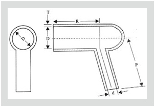
A panel gives a termination no room. Bushing centres are fixed by the switchgear maker, and the manufacturer's three protector charts publish them at 95 mm for the GTPE-1 elbow and at 110 mm and 125 mm for the 12 kV and 24 kV boot pairs. At that spacing, clearance inside the box sits below what the same voltage would be given in open air.
Insulation is therefore added, not assumed. The published reasons for fitting it are specific: flashover under high humidity, rodent or bird intervention, and surge impulse.
Two inputs come off the cable schedule — construction and conductor cross-section. Two come off the panel drawing — Umax and the gland-plate-to-bushing dimension. Miss the fourth and no tail length can be specified, which makes the kit code a guess.
Four answers, and the panel condition that selects each
Not grades of one product. The first can be specified together with either of the next two.
Indoor termination kit
The starting point, not an accessory. Indoor builds carry the GXE or GPE code, and the GXO/E series is published as supplied without rain sheds. Stress control and earthing are identical to the outdoor build.
Heat-shrink boot over the bushing
Cross-linked non-tracking polyolefin, internally coated with water-resistant red mastic. Right angle GRB-1 to GRB-3, straight GSB-1 to GSB-3, each charted by supplied and recovered bore — GRB recovers to 35, 37 or 72 mm at the throat. Shrink temperature 125 °C, dielectric strength 15 kV/mm minimum.
EPDM barrier system
A moulded insulating boot with grommets and a plug, stated to fit sector-shaped cable. Re-usable, and published as facilitating direct voltage testing — usually the deciding property, not dielectric margin. The published cross-section range differs between the datasheets and the product pages.
Screened separable connector
Available only where the equipment presents an EN 50180 and EN 50181 type C bushing. Against a cable box with a bolted palm this option does not exist, and the choice narrows to the three above.
By enclosure: what is terminated, and what is added
Read the first column off the general arrangement. The rest follows from it.
| Enclosure on the drawing | Termination method | Insulation added inside | Published figure that governs it |
|---|---|---|---|
| Switchgear panel with a cable box | Indoor heat-shrink kit, GXE or GPE code | Right-angle or straight boot over each bushing connection | No tracking or erosion up to 3.25 kV for 20 minutes [ASTM D2303] |
| Compact entry box or motor terminal box | Indoor heat-shrink kit sized on the cable schedule | EPDM barrier system: boot, grommets and plug | Bushing centre distance 95 mm (GTPE-1), 110 mm at 12 kV, 125 mm at 24 kV |
| Ring main unit with a type C bushing | Screened separable connector, plugged on | None — the connector body carries its own earthed screen | 630 A to 24 kV, 630/1250 A to 36 kV, to IEC 60502.4 |
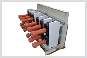
| Draw-out breaker cubicle | Not a cable termination at all | Insulation boot over the breaker's draw-out contacts | Dielectric strength 25 kV/mm minimum [IEC 243], meeting ANSI C37.20.2 |
What three of the answers look like
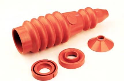
Tail length is set by the panel, not by the kit
Tail length is the one kit dimension the panel drawing decides. Measure gland plate to bushing palm, add the lug barrel, then compare that against the published indoor cut before any code is raised.
GXOS/E-1236 publishes indoor tails of 450 mm at 12 kV, 550 mm at 24 kV and 700 mm at 36 kV, and the GXO/E series publishes special tail lengths as available on request — the route when the cable box is deeper than the standard cut. Series-by-series figures are tabulated on indoor or outdoor termination.
A short tail is not recoverable with what is in the van. A long one is bent into the box, and the bend eats the clearance the boots were bought to protect.
Sources disagree — straight or right angle
The Cable Terminal Protector page describes the system as insulating right-angle connections, then publishes two selection charts on that same page: a straight pair, GSTB-1 and GSTB-2, alongside the right-angle GRTB-1 and GRTB-2. Both are reproduced as published, neither averaged. A panel presenting straight bushing palms needs the profile confirmed in writing against the code.
The draw-out breaker on the same requisition
A breaker cubicle is not a cable termination, but it sits in the same lineup and is routinely left out until the type-test clause is drafted. Published properties of the insulation boot for draw-out circuit breakers:
- Non-tracking cross-linked polyolefin, halogen free and flame retardant; oxygen index ≥ 28 [IEC 93]
- Dielectric strength 25 kV/mm minimum [IEC 243]
- Continuous temperature limit −40 to +105°C [IEC 216]
- No tracking, erosion or flame failure up to 3.25 kV for 20 minutes [ASTM D2303]
- Resists acid, alkali and salt corrosion, and stated to be highly resistant to UV and ozone, so one part covers indoor and outdoor cubicles
- Fitted or stripped in minutes, complete with fasteners, as often as required — meets ANSI C37.20.2, cited from the manufacturer's page
Not published — ask the manufacturer
Both boot profiles are fully dimensioned — supplied and recovered bore, leg lengths and wall thickness, reproduced on bushing boots — but no voltage figure is published against any boot code, so a GRB-2A cannot be argued onto a 24 kV board from the chart alone. Nor is any pollution class stated for the boots or the barriers, and no creepage distance is published for either. Send the bushing outside diameter, the lug width, the phase centre distance and Um, and ask for the size and the class confirmed together.
Where the job hands off
A ring main unit is a switchgear panel with a different cable interface. Once the drawing shows a type C bushing the answer set changes: the connector makes the termination and carries its own earthed screen, so nothing is fitted over it. One figure does not carry across — the GTPE-500 elbow fits RMU type C bushings and is charted at 95 mm centres, but it is stated not to be a touch-proof product, so it answers a clearance problem and never a dead-front clause. See RMU cable terminations.
The barrier system also names motor terminal boxes and distribution transformers among its applications, so the part is unchanged there; what changes is the equipment side and the earthing around it, at transformer and motor terminations.
Questions raised at the panel-drawing stage
Does a bushing boot change the termination's type-test result?
Can the terminal be voltage-tested once the insulation is fitted?
Is a terminal protector touch-proof?
The panel is indoors and dry. Is anything needed beyond the indoor kit?
Send the panel GA alongside the cable schedule
This job is specified from two drawings at once, and an enquiry carrying only one comes back as a question. Bushing centre distance and the gland-plate-to-bushing dimension are the two figures almost always missing.