Kit component
Grading the field at the screen cut-back
Four inputs decide whether the graded component is in your kit at all: insulation screen present or absent, screen type, core count and Umax.
Insultube-Stress heat-shrink stress control tube
Radiation cross-linked polymeric tube, published as controlling high electrical stress at insulation-screen terminals and at power cable joints up to 36 kV. It grades the field; the sleeves that follow it do the insulating.
- Ships inside the GXO/E, GXOS/E and GPO/E kits rather than as a kit itself
- Stress control mastic is the companion item, listed separately in kit contents
- GVOT integrated stress control sleeve is the alternative, published to 24 kV
| Material | Radiation cross-linked polymeric compound |
|---|---|
| Published rating | Insulation-screen terminals and cable joints up to 36 kV |
| Operating temperature | -40 °C to 100 °C |
| Dielectric constant | 15 (min.) [ASTM D150] — the high permittivity that does the grading |
| Minimum shrink temperature | 100 °C |
| Fully recovered at | 130 °C |
| Standard colour | Black |
| Published sizes | GST30/12, GST40/18, GST50/20, GST60/25 |
What the cut-back does to the field
A screened MV cable is a coaxial capacitor along its whole length. The insulation screen holds the outer surface of the insulation at earth potential, so the field sits radially inside the wall. Terminating means removing that screen over the exposed core, and the geometry then ends at a hard circumferential edge.
Equipotential lines crowd into the few millimetres either side of that edge, and the field component running along the surface rises sharply exactly where insulation first meets air. Nothing in a heat-shrink kit restores the screen. This component redistributes what the edge concentrates, so the potential falls over a usable distance instead of over a step. The maker's own Insultube-Stress page carries the product as published.
Two engineering answers to one discontinuity
Geometric. A stress cone flares a profile outward from the screen edge, lengthening the surface path across which the potential falls. Anyone searching for a stress cone termination kit wants this answer. In this catalogue it appears as the stress-cone adapters published with the screened separable connector body, covering 25 to 400 sq mm up to 24 kV — never inside a heat-shrink kit.
Material. A high-permittivity compound over the edge redistributes the field by changing the medium rather than the shape. Every heat-shrink termination in this range takes that route, in two forms: tubing that recovers over the edge, and mastic that fills the step beneath it. They are separate lines in the same contents list.
A third arrangement moves the material answer inside another part. GVOT is published as an integral stress control sleeve to 24 kV, and Soloterm carries an integrated varistor coating bonding to insulation and screen from within, published to 33 kV. Neither leaves a discrete tube for the jointer to fit. How each technology grades the field sets the three against each other.
What it looks like once it is on
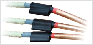
The black band on each core is the tube, recovered over the point where the screen ends. It is short, its length is set by the kit rather than by the installer, and everything forward of it is built on top once it has cooled.
Where the mastic and the tube sit in the build
Four operations, in this order. Dimensions belong to the kit instructions for that voltage class.
Cut the insulation screen back
The distance is fixed by the kit for the class it was bought for. It is the one dimension on the core that is not the installer's to choose.
Fill the step with stress control mastic
The semi-conducting screen sits proud of the insulation, so removing it leaves a shoulder. Mastic is cold-applied and hand-formed into that shoulder to leave no air behind it, and contents lists show it as a separate item from the plain mastic sealing tape used at the lug.
Recover the tube over the filled step
Heat until the wall has conformed to the profile underneath, not merely until it grips. Minimum shrink temperature is 100 °C and full recovery is at 130 °C; GXO/E kits ship temperature-sensitive paint that changes colour when shrinking is complete.
Build the insulation and weather layers on top
Non-tracking sleeve, breakout and rain sheds follow, answering surface tracking rather than field grading. The installation sequence covers the whole build.
Insultube-Stress selection chart
| Code | D (min.) | d (max.) | T (±10%) |
|---|---|---|---|
| GST30/12 | 30 | 12 | 2.3 |
| GST40/18 | 40 | 18 | 2.4 |
| GST50/20 | 50 | 20 | 2.4 |
| GST60/25 | 60 | 25 | 2.4 |
Published on the manufacturer's Insultube-Stress page. D is the internal diameter as supplied, d the internal diameter after free recovery, T the recovered wall. All dimensions in mm. Both lengths photographed on that page — GST40/18 and GST60/25 — are rows in it.
Physical and thermal properties
| Property | Value | Standard |
|---|---|---|
| Tensile strength | 12 MPa (N/mm²) (min.) | ASTM D638 |
| Ultimate elongation | 300 % (min.) | ASTM D638 |
| Longitudinal change | −10 % (max.) | ASTM D2671 |
| Hardness | 45 ± Shore D | ASTM D2240 |
| Accelerated ageing | 120 °C for 500 h | ASTM D2671 |
| Tensile strength after ageing | 10 MPa (N/mm²) (min.) | ASTM D638 |
| Ultimate elongation after ageing | 300 % (min.) | ASTM D638 |
| Low-temperature flexibility, −40 °C for 4 h | No cracking | ASTM D2671 |
| Heat shock, 250 °C for 30 min | No cracking or flowing | ESI 09-11 |
| Shrink temperature | 125 °C | IEC 216 |
| Continuous temperature limit | −40 °C to +100 °C | IEC 216 |
Reproduced from the technical specification on the manufacturer's Insultube-Stress page. Tensile and elongation appear twice; the second pair is the post-ageing figure.
Electrical properties — and the one figure that matters most
| Property | Value | Standard |
|---|---|---|
| Volume resistivity | 1 × 10⁷ Ohm·cm (min.) | ASTM D257 |
| Dielectric constant | 15 (min.) | ASTM D150 |
Only two electrical rows are published, and the second is the whole mechanism. A dielectric constant of 15 minimum against 2.3 for the XLPE it sits on is what pulls the equipotential lines apart at the cut edge. Volume resistivity is seven orders of magnitude below an insulating compound's, which is the point: the tube is deliberately slightly conductive.
Sources disagree — 125 °C or 100 °C to 130 °C
The same manufacturer's page states it twice and differently. Its feature list gives minimum shrink temperature 100 °C and minimum fully-shrunk temperature 130 °C. Its technical specification, four rows lower, gives shrink temperature 125 °C [IEC 216]. Both are reproduced above and neither is averaged. The gap matters on site because the visible test — the wall gripping the core — happens well below 130 °C, and an under-recovered tube leaves the void it exists to remove. Work to the 130 °C figure until the manufacturer says otherwise; it is the conservative one.
Sources disagree — 36 kV or 66 kV
The Insultube-Stress product page rates the tube for insulation-screen terminals and cable joints up to 36 kV. The component list on the same site rates non-tracking tube and stress control tube to 66 kV, beside red insulation tube at 66 kV. Both are published, neither is withdrawn, and they are reported as found rather than averaged. Not in dispute: every kit this tube ships inside stops at 36 kV. What 66 kV does and does not mean here.
Not published — ask the manufacturer
Two figures a clause wants at this point exist in no published document, and neither is estimated here: a grading factor against the unmitigated edge, and any rule relating recovered length to system voltage. One more is a mapping rather than a value — the selection chart bands the four GST codes on core diameter alone, so nothing published tells you which code ships inside which kit code, or which one a given cable size takes. The permittivity is not on this list: the manufacturer publishes a dielectric constant of 15 minimum [ASTM D150], which is the figure the grading argument rests on.
Four ways the stress control is defeated on site
Each of these leaves a termination that passes a visual inspection.
- Cut-back distance taken from the wrong class. A 12 kV dimension used on a 24 kV core shortens the grading length while the finished assembly still looks correct.
- Mastic omitted or under-filled at the screen step. The remaining void sits precisely where the surface field peaks, which is the one place air is least wanted.
- Tube heated until it grips but not until it recovers. Short of 130 °C the wall bridges the shoulder instead of conforming to it, and the void moves underneath the tube.
- Semi-conducting residue or solvent film left on the insulation. GPO/E kits list cleaning solvent as an installation aid for this reason.
Which kits carry it, and the one that does not
It is never bought alone here. It arrives as a named line in a kit's contents.
- GXO/E-1112, GXO/E-1524, GXO/E-3336 and GXOS/E-1236 — XLPE and EPR, 12 to 36 kVStress control tubing is named in all three 3-core kits; single-core GXOS/E-1236 lists a stress control sleeve and stress control mastic together.
- GPO/E-1112, GPO/E-1524, GPO/E-3336 — PILC, 12 to 36 kVA stress control sleeve at 12 kV, stress control tubing at 24 and 36 kV, alongside the oil barrier sleeve paper cable needs.
- GLT-1100 — 1.1 and 3.3 kV, the exceptionContents list no stress control component of any kind. Unscreened cable has no screen edge to grade.
- Joint kits carry the same pairGXS/1236 lists a stress control sleeve with stress control mastic; GXSS-1236 lists stress control mastic for the ferrule region plus stress control tubing.
- The sleeves that go on after itDifferent compounds, solving a surface problem rather than a field problem.
- The manufacturer's component listSource for the 66 kV material rating and for the GVOT integrated sleeve.
Questions this component raises in specification review
Is a stress control tube the same thing as a stress cone?
Can the mastic be omitted if the tube overlaps far enough?
The material is published at 66 kV. Can it terminate a 66 kV cable?
How do stress control mastic and mastic tape differ on a bill of materials?
Checking a kit against a cable, or drafting the clause?
A useful message names the cable make-up first: insulation type, core count, mm², Umax, indoor or outdoor. With those five, published kit contents can be checked line by line against what the construction needs.